Suspension System
Design Phase: Prototype v4
This ongoing personal engineering project focuses on the design and development of a front double-wishbone suspension system for a GT-style race car. The project began with research into suspension architecture, vehicle dynamics and the advantages of double-wishbone systems, with particular focus on camber control, tyre contact and suspension behaviour throughout travel.


I developed the suspension geometry from initial concepts into a complete SolidWorks CAD assembly, designing components including the upper and lower wishbones, steering knuckle, hub and coilover mounting system. The design process required consideration of track width, wheel size, ride height, suspension travel, camber gain, caster, steering geometry and component packaging.


A major part of the project has been an iterative prototyping process. I have produced multiple versions of the suspension components and assemblies, using the results from each prototype to identify and correct design issues. Earlier prototypes highlighted problems with structural integrity and insufficient rigidity, while other iterations produced an incorrect camber angle once the complete suspension system was assembled. These results led to modifications to component geometry, mounting positions and overall suspension geometry before producing subsequent prototypes.


The project has also significantly improved my understanding of engineering tolerances and their practical application. Through repeated assembly and testing of 3D-printed components, I developed a better understanding of how dimensional tolerances, clearances and fit between components affect the performance and functionality of a mechanical assembly. I used these lessons to refine the CAD models and improve the fit and movement of later prototypes.

Exploded view of wheel hub, upright, axle shaft and driveshaft
The components are modelled individually in SolidWorks before being assembled using appropriate mates to replicate their intended movement. Scaled 3D-printed prototypes allow me to physically evaluate the design, identify issues that may not be apparent in CAD and validate changes before progressing further.

Improved Coilovers to fit suspension geometry


Assembled View of upright, wheel hub and axle shaft
The project is continuing to develop, with future work focused on further suspension kinematic analysis and optimisation of the geometry for camber control, handling performance, structural integrity, weight and manufacturability.
3 iterations of the lower wishbone changing the design to induce static negative camber
Multiple prototypes for the wheel hub and the washer to fit the wheels on and so the drive shaft doesnt fall out


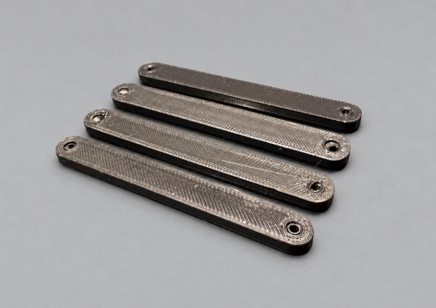

First design of the body that had to be changed due to the coilover connections not fitting at the right angle, the upper wishbones would have to be bigger resulting in more unsprung mass and there would be no space for a driveshaft hub
Displaying the upright design featuring two ball bearings so the axle shaft could spin
Multiple designs for the upper control arms with ball bearings imbedded in them, experimenting with different tolerances to achieve consistent 3d printed results
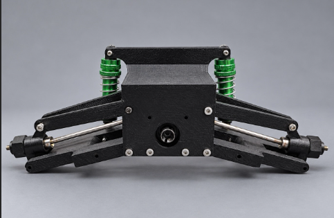


Multiple angles of the fully assembled system showcasing all components including the driveshaft hub, the main body, both sets of wishbones and uprights.